Crosstalk refers to the unwanted transfer of signals between communication channels, typically occurring when electromagnetic interference (EMI) from one wire pair induces a signal in an adjacent pair. Crosstalk in Ethernet cables refers to the unwanted transfer of signals between adjacent wire pairs within the same cable. This interference occurs when the electromagnetic field generated by a signal in one pair induces a signal in a neighbouring pair, leading to noise, data corruption, reduced transmission speeds, and increased error rates. Crosstalk can degrade network performance by increasing error rates and reducing signal clarity, especially at higher transmission speeds. Ethernet cables like Cat5e and Cat6 are designed with twisted pairs and, in some cases, internal separators or shielding to minimize this effect and maintain signal integrity.
The same principle of crosstalk applies to analogue signals as well as audio signals. In analogue audio systems, crosstalk can occur between channels—such as left and right stereo tracks—resulting in a “bleed” of sound from one channel into another reducing audio quality. This is particularly noticeable in poorly shielded cables or tightly packed audio circuits, where electromagnetic interference is not adequately controlled. Just like in Ethernet cabling, minimizing crosstalk in audio systems is essential for preserving clarity, channel separation, and overall sound quality.
Types of Crosstalk
Near-End Crosstalk (NEXT) : Occurs when the interference is measured at the same end of the cable as the signal source. It’s a major concern because it can corrupt the signal before it even leaves the cable.
Far-End Crosstalk (FEXT): Happens when the interference is measured at the opposite end of the cable from the signal source. It becomes more significant over longer cable runs.
Alien Crosstalk (AXT): Interference caused by unwanted signals in adjacent cables, not just within the same cable. This is especially problematic in high-density installations like data centres.
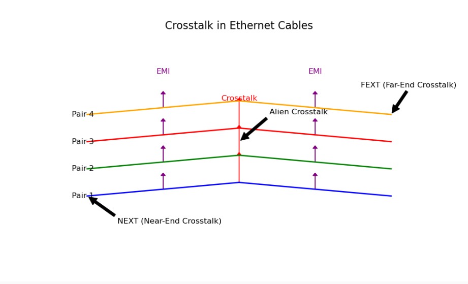
Labelled diagram that visually explains crosstalk in Ethernet cables:

Cross Talk Diagram Highlights:
- Twisted Pairs: Represented in different colors to show the four pairs inside a typical Ethernet cable.
- EMI Arrows: Purple arrows indicate external electromagnetic interference.
- Crosstalk Arrows: Red arrows show how signals from one pair can interfere with others.
- NEXT (Near-End Crosstalk): Occurs near the signal source.
- FEXT (Far-End Crosstalk): Happens at the far end of the cable.
- Alien Crosstalk: Interference from adjacent cables, not just within the same cable.
Cross Talk Types Summary Table
| Type | Description | Where It Occurs |
|---|---|---|
| NEXT (Near-End Crosstalk) | Interference measured at the transmitting end | Patch panels, short runs |
| FEXT (Far-End Crosstalk) | Interference measured at the receiving end | Long cable runs |
| ELFEXT | FEXT adjusted for signal attenuation | Long-distance performance |
| AXT (Alien Crosstalk) | Interference from adjacent cables | High-density bundles |
How Crosstalk Happens: Step-by-Step Breakdown
1. Signal Transmission and Electromagnetic Fields
In Ethernet cables, data is transmitted using electrical signals that travel through copper conductors. These signals are typically differential, meaning each pair of wires carries two complementary voltages (one positive, one negative). This method enhances noise immunity and allows the receiver to detect the difference between the two signals, rather than their absolute values. As an electrical signal moves through a conductor, it generates an electromagnetic field (EMF) around the wire. This field consists of
- An electric field, caused by the voltage difference between the wires.
- A magnetic field, caused by the current flowing through the wires.
These fields oscillate with the signal’s frequency and can extend beyond the wire itself, especially at higher frequencies.
2. Proximity of Wire Pairs
In Ethernet cables, four twisted pairs of wires are tightly packed together. Because of this close proximity, the electromagnetic field from one pair can extend into the space occupied by adjacent pairs.
3. Inductive and Capacitive Coupling
Crosstalk arises from two main coupling mechanisms:
- Inductive Coupling: A changing current in one wire pair induces a voltage in a nearby pair through magnetic fields.
- Capacitive Coupling: A voltage difference between adjacent wires creates an electric field, which can induce a current in the neighboring pair.
These couplings cause a portion of the signal from one pair (the aggressor) to appear on another pair (the victim), even though they are not electrically connected.
4. Signal Interference
The induced signal on the victim pair adds noise to the intended signal being transmitted on that pair. This can distort the data, increase the bit error rate (BER), and reduce the signal-to-noise ratio (SNR).
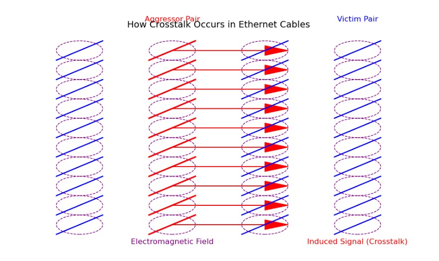
Diagram of How Cross Talk Occurs

How Cross Talk Occurs Diagram Highlights:
- Red twisted pair: The “aggressor” pair transmitting a signal.
- Blue twisted pair: The “victim” pair receiving unintended interference.
- Purple dashed circles: Represent the electromagnetic field generated by the aggressor pair.
- Red arrows: Show how the signal is unintentionally induced into the adjacent pair, causing crosstalk.
This visual illustrates how proximity and electromagnetic coupling between wire pairs can lead to signal interference.
What Factors Influence Crosstalk?
Crosstalk is primarily caused by electromagnetic coupling between adjacent wire pairs. The degree to which this occurs depends on several physical and electrical factors:
1. Twist Rate of Wire Pairs
- Definition: The number of twists per unit length (typically per inch or per meter).
- Impact: Tighter twists reduce the loop area between conductors, which minimizes the magnetic field and reduces inductive coupling.
- Example: Cat6 cables have more twists per inch than Cat5e, which significantly lowers both internal and alien crosstalk.
2. Pair Separation and Cable Geometry
- Definition: The physical distance between twisted pairs within the cable.
- Impact: Greater separation reduces capacitive and inductive coupling between pairs.
- Design Feature: Cat6 cables often include a central spline or cross-divider to maintain consistent spacing and reduce internal crosstalk.
3. Shielding
- Types:
- UTP (Unshielded Twisted Pair): No shielding; relies solely on twist geometry.
- STP (Shielded Twisted Pair): Includes foil or braided shielding around individual pairs or the entire cable.
- Impact: Shielding blocks external electromagnetic interference (EMI) and reduces alien crosstalk from adjacent cables.
- Use Case: Shielded cables are preferred in high-interference environments like industrial settings or data centers.
4. Cable Category and Manufacturing Standards
- Definition: Higher-category cables (e.g., Cat6, Cat6a) are built to stricter performance specifications.
- Impact: These standards enforce tighter tolerances for twist rates, pair balance, and impedance, all of which reduce crosstalk.
- Example: Cat6a is specifically designed to eliminate alien crosstalk over 100 meters for 10GBASE-T.
5. Installation Practices
- Impact: Poor installation can introduce or worsen crosstalk.
- Excessive untwisting at termination points increases susceptibility.
- Tightly bundling multiple cables can increase alien crosstalk.
- Running cables near power lines can introduce EMI.
- Best Practices: Maintain twist integrity up to the termination point, avoid sharp bends, and separate data cables from power lines.
6. Cable Length and Signal Frequency
- Impact:
- Longer cables increase the opportunity for signal degradation and crosstalk accumulation.
- Higher frequencies (used in faster Ethernet standards) are more susceptible to crosstalk due to increased EMI radiation and coupling.
- Example: 10 Gbps Ethernet (10GBASE-T) uses frequencies up to 500 MHz, making crosstalk control critical.
7. Connector and Patch Panel Quality
- Impact: Poorly designed or low-quality connectors can introduce impedance mismatches and increase NEXT and FEXT.
- Solution: Use certified components that match the cable category and maintain consistent electrical performance.


