A Comprehensive Guide to RJ45 Ethernet Pinouts and Colours. Understanding Straight-Through and Crossover Cables for Ethernet Networks.
The RJ45 connector is a standardized interface used in Ethernet networking. ‘RJ’ stands for ‘registered jack’, which is a standardized network interface for connecting voice and data devices. RJ45 connectors have eight contacts, which correspond to the eight wires in the cable and are essential for establishing correct wiring patterns (pinouts) to ensure reliable network data transmission. RJ45 connectors are commonly used to terminate twisted-pair cables, such as CAT5e and CAT6, and are essential for creating reliable wired local area networks.
Ethernet cable is the typical blue cabling you see connecting different devices to the wall, switch or patch panel. Ethernet cable has 8 wires arranged as four pairs of twisted wires, known as twisted pairs. The twists in these pairs help minimize interference and maintain signal integrity, which is crucial for high-speed data transmission. Each wire and pair are identified by Ethernet cable colours, following a standardized color scheme (such as T568A and T568B) to ensure correct wiring.
This guide provides detailed information on RJ45 Ethernet pinouts and colours and their correct order to ensure a reliable connection. It covers both straight-through cables and crossover cables on both industry standards.
Understanding RJ45 Connectors
RJ-45 connectors or RJ-45 Plugs have eight pins, which are used to terminate the individual pairs of wires inside an Ethernet cable. These modular connectors are typically crimped onto the end of the cable with a specialised crimping tool, allowing for secure connections and data transmission to network devices like routers, switches, computers, and other network equipment.
RJ45 Pinout Standards
There are two main wiring standards for RJ-45 connectors: T568A and T568B. These standards define the pinout configuration for the wires within the cable. While both standards are widely used, T568B is more common in the United States whilst in Australia we typically use T568A. T568B is typically preferred in commercial networks and office environments, while T568A is more common in residential or legacy systems. You might find many prebuilt cables you get with equipment are wired for T568B, this doesn’t matter though, it doesn’t matter what wiring scheme is used they will all work the same. However, maintaining consistency in wiring standards is crucial for compatibility and reliable connectivity, especially in structured cabling systems.
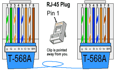
T568A Wiring Standard – The preferred Standard for Australia
- Pin 1: White/Green
- Pin 2: Green
- Pin 3: White/Orange
- Pin 4: Blue
- Pin 5: White/Blue
- Pin 6: Orange
- Pin 7: White/Brown
- Pin 8: Brown
T-568A RJ-45 Connector

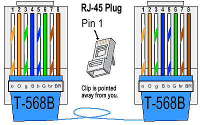
T568B Wiring Standard
- Pin 1: White/Orange
- Pin 2: Orange
- Pin 3: White/Green
- Pin 4: Blue
- Pin 5: White/Blue
- Pin 6: Green
- Pin 7: White/Brown
- Pin 8: Brown
T-568B RJ-45 Connector

Tools and Equipment for Ethernet Cable Assembly

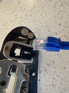
Assembling Ethernet cables requires a few essential tools to ensure a professional and reliable result. The most important piece of equipment is the RJ45 crimping tool, which is used to securely attach the RJ45 connector to the end of the cable. Before crimping, wire strippers are used to carefully remove the outer jacket of the cable, exposing the individual wires inside without damaging them. Cable cutters help you trim the cable to the desired length, making it easier to manage your network cabling. Once the cable is assembled, a cable tester is invaluable for checking that each wire is correctly connected and that the cable will function properly in your network. Using the right tools not only makes the assembly process smoother but also helps prevent common wiring mistakes that can lead to unreliable connections.
RJ45 Straight-Through Cables
Straight-through cables, also known as straight cables, are the most common cables you will create and are the standard for Ethernet connections. Straight-through network cables are the ones used to connect all your peripherals or network devices, such as a computer, printer, modem, or router to a centralized switch. These cables are typically referred to as “Patch Cable” or “Patch Cords” as they patch the network devices into a switch or wall plug. In a straight-through cable, both ends of the network cable follow the same wiring standard, either T568A or T568B.
Correct wiring is especially important for high speed networks, such as those using Cat5e or Cat6 cables, to maintain signal integrity and reliable performance. Wiring diagrams are useful tools for ensuring correct assembly of straight cables and adherence to wiring standards. Keystone jacks are commonly used with straight cables in structured cabling systems to create reliable Ethernet connections. Proper wiring and the use of twisted pairs help reduce electromagnetic interference, ensuring reliable data communication.
Uses of RJ45 Straight-Through Cables
- Connecting a computer to a network switch or hub
- Connecting a router to a modem
- Connecting a network switch to a router
Wiring a RJ45 Straight-Through Cable
To create a straight-through cable, start by stripping about an inch of the outer jacket from both ends of the cable using a wire stripper. Carefully untwist the wire pairs and arrange the eight wires according to your chosen wiring standard—either T568A or T568B—making sure the color order is correct on both ends. Trim the wires so they are even and will fit neatly into the RJ45 connector. Insert the wires fully into the connector, ensuring each wire reaches the end and stays in the correct order. Use a crimping tool to firmly attach the connector to the cable. Before finishing, double check that the wiring matches the selected standard on both ends to guarantee a properly wired straight through cable.
Crossover Ethernet Cable
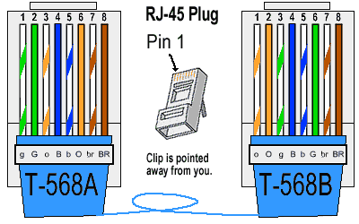
Crossover cables are used to connect similar devices directly, such as connecting two computers or two network switches, allowing one device to communicate with another without an intermediary like a switch or hub. In an Ethernet crossover cable, one end follows the T568A standard, while the other end follows the T568B standard. This configuration allows the transmit and receive signals to be correctly aligned, so data is transmitted between the devices by crossing the relevant pairs.
Uses of Ethernet Crossover Cables
- Connecting two computers directly without a switch or hub
- Connecting two network switches directly
- Connecting two routers directly
Wiring an Ethernet Crossover Cable
To wire a crossover cable the only difference is to use the T568A standard on one end and the T568B standard on the other end. This creates the necessary crossover of the transmit and receive pairs.
Pinout Colour Coding Comparison for Crossover Cables
- Pin 1 (T568A: White/Green) connects to Pin 3 (T568B: White/Green)
- Pin 2 (T568A: Green) connects to Pin 6 (T568B: Green)
- Pin 3 (T568A: White/Orange) connects to Pin 1 (T568B: White/Orange)
- Pin 4 (T568A: Blue) connects to Pin 4 (T568B: Blue)
- Pin 5 (T568A: White/Blue) connects to Pin 5 (T568B: White/Blue)
- Pin 6 (T568A: Orange) connects to Pin 2 (T568B: Orange)
- Pin 7 (T568A: White/Brown) connects to Pin 7 (T568B: White/Brown)
- Pin 8 (T568A: Brown) connects to Pin 8 (T568B: Brown)

Common Mistakes in Ethernet Cable Wiring
When assembling Ethernet cables, several common mistakes can compromise your network’s performance. One frequent error is arranging the wires in the wrong order, which can disrupt data signals and prevent devices from communicating. Uneven wire lengths may cause some wires to miss the connector contacts, resulting in unreliable connections. Excessive untwisting of the wire pairs can increase electromagnetic interference, reducing signal integrity and potentially causing data loss. Weak or loose crimps can lead to wires disconnecting under tension, especially if the cable is moved or pulled. Finally, neglecting to test the cable with a cable tester can leave wiring faults undetected until the cable is already in use. Avoiding these mistakes is key to building a robust and reliable Ethernet network.
Cable Testing and Verification
Before deploying Ethernet cables in your network, it’s essential to test and verify each cable to ensure it’s functioning correctly. A cable tester is a simple but powerful tool that checks the continuity of each wire and confirms that all connections are properly made. It can quickly identify issues such as open circuits, shorts, or miswires, which could otherwise lead to network problems. Testing your cables before installation helps prevent future connectivity issues and saves time troubleshooting. Regular cable testing is also a good practice for ongoing network maintenance, helping to catch and resolve problems early to keep your Ethernet network running smoothly.
Cable Management for Reliable Networks
Good cable management is crucial for maintaining a reliable and efficient network. Organizing Ethernet cables with patch panels, cable ties, and cable organizers helps reduce clutter and prevents cables from becoming tangled or damaged. Properly managed cables are less likely to suffer from electromagnetic interference, which can degrade signal quality and cause network issues. When installing cables, avoid bending them sharply or pulling them too tightly, as this can damage the internal wiring. Keep Ethernet cables separated from electrical wiring to further reduce the risk of interference. Labeling both ends of each cable makes future testing, troubleshooting, and upgrades much easier. By following these cable management best practices, you can ensure your network cabling remains organized, efficient, and reliable.

RJ45 Pinouts, Colours – Summary
Understanding RJ45 Ethernet pinouts and colors is essential for anyone working with network cabling. By following the correct wiring standards for straight-through and crossover cables, you can ensure reliable and efficient network connections.
Most modern devices support features like auto MDI-X, which allow them to automatically detect and configure the correct connection type, reducing the need for crossover cables. However, when working with older equipment, it is important to pay careful attention to cable standards and configurations to ensure compatibility.
Whether you are setting up a home network or managing a large-scale enterprise system, this knowledge will help you create robust and effective networking solutions.


